
NOTE – THE TWO IS AN UPDATED VERSION OF THE ONE AND THE DESIGN INCORPORATED ALMOST ALL OF THE ONE’S CIRCUITRY WITH IMPROVEMENTS, ADDITIONS, AND MODIFICATIONS. UNLESS STATED OTHERWISE, MODIFICATIONS AND TWEAKS ARE THE SAME FOR EACH RADIO.
It seems the first thing everyone wants to do when trying to resolve an issue with a tube radio is replace tubes. Most of the time this does not fix the problem. The small receiving tubes are much more reliable than power amplifier tubes. Yes, tubes do go bad. Sometimes they become gassy. If the getter (silver or dark colored spot) in the tube is transparent, white, or has white around the edges, it’s either bad or will soon go bad. Heater to cathode shorts can cause hum and I’ve seen that once with the 6AW8 in a Johnson. Before ordering a replacement tube(s) look for other issues as it may save you a few dollars. Some radios in my collection still have original EF Johnson tubes in them and they work as they should.
Corrosion on the tube pins or socket contacts can cause noise. Usually polishing the tube pins with an abrasive SUCH AS FINE SANDPAPER and then a very light application of Deoxit fixes the most stubborn cases.
MOST IMPORTANT!!!! Messenger One and Two radios do not have an internal fuse. If you do not use the Elmenco or Dare fused power plug you will need to install a fuse holder in the hot side of the power cord (changing it to a “polarized plug) even if it is nothing more than a pigtail fuse under the chassis inside the radio. Do not operate your radio without a fuse or a fuse larger than about 1.5 amps in the AC line. The stock fuses are 1 amp. If you desire to add an earth ground with a 3 wire cord, the green wire (earth ground) would attach to the chassis ground or Pin 2 in the 9 pin connector. Since the Johnson uses a transformer, the chassis is not “hot” unless there is an issue with a bypass capacitor on the AC line, the transformer, or wiring and on/off switch related to the AC line.
Resistor Check List – Take a few minutes to do this as it can save you time later. Check in-circuit all the resistors that are 100K ohm or more in the area of the detector, ANL, and 12AU7 (V10). Also the 470K ohm resistors that on V5 6AW8 and V6 12AB5 tubes. Also check R40, the 390K screen resistor for V7 8077/7054/12BY7 tube. Be more concerned about any resistor reading higher than reading lower in value. I would recommend buying an assortment of 100k, 220k, 330k, 390k, 470k, 820k and 1 meg ohm resistors with about 5 times more 470K ohm resistors than what you think you might need, especially if you are working on several of these radios. There are several 470K resistors in each radio.
Let the radio “COOK” FOR SEVERAL HOURS!!! I’ve found that sometimes the RX mixer and IF transformers will change tuning slightly after being on for several hours. Once you are satisfied with your conversion, put the case on, and let it heat up and cook out any moisture that has accumulated over the years. Don’t walk off and leave it totally unattended in case something goes wrong. If you begin to smell an odor and/or suddenly hear a pop or hum start, best to turn it off ASAP, disconnect the AC, and then troubleshoot. The filter and paper capacitor failures I experienced did not result in dramatic effects such as explosions, fire, or lots of smoke. The cases swelled or split, there was an odor released, and the radio starting having hum in the instance of new electrolytic capacitors failing.
NOISE WHEN TAPPED OR RADIO IS MOVED – Corrosion on the tube pins and mating socket connections can cause issues with filament not lighting or noise if the tube or chassis is tapped. Try rocking each tube in the socket and if the filament lights or there is lots of noise, remove the tube and buff the pins on the tube lightly to remove any corrosion. A light application of Deoxit can be applied to each pin. Then insert the tube back into the socket and rock it around. That usually repairs the most stubborn cases of noise when the tube is rocked in it’s socket.
No Power Output: If the TX oscillator is working properly there is a 100 ohm 2 watt resistor that feeds modulated B+ to the 7061/6CM6 plate from the often jumpered 3900 ohm resistor. If the modulated B+ on this resistor is very low on the plate end when keyed, more than likely you have an open 100 ohm resistor or it’s the winding in the modulation/audio output transformer. The RX will work fine if the modulator winding is open. You can verify if the winding is open by measuring the resistance from the 6200 ohm resistor that is connected to pin 9 of the 12AB5/6CM6 and the 3900 ohm 10 watt resistor (or jumper in it’s place) that supplies modulated B+ to the PA. Do this with the power disconnected! If the winding is open, it’s a parts radio unless you have a donor or want to try rewinding or repairing the audio transformer.
IF TRANSFORMER ISSUES: If any of the 455 khz IF transformers don’t seem to want to tune up, check the cathode and plate resistors of the tubes feeding them for open or drifted values. Only change the IF transformer as a last resort as they seem to give almost no problems other than someone breaking the cores and causing them to stick or the rare cases I have found below. Those same resistors will also lower the gain and RX sensitivity will suffer.
I’ve found (3) 455khz IF transformers in Ones and (1) in a Two that would not tune. Either the cores bottom out before peaking or the peaks are very broad and not sharp. As the core bottoms out, the sensitivity was increasing in most cases. Replacing with salvaged IF transformers (hex core type) resulted in the issue being resolved. There are no capacitors external to them that affect the frequency response.
In Sept of 2021, a Messenger II crossed my bench. The 1st 455khz IF transformer (T1) after the mixer tube was tuning with the slugs almost touching each other. The peaks were very broad and not sharp. RX sensitivity was not what it should have been. I no longer had any IF transformers left from salvaged radios so I improvised. If you look at a I, there are 2 less IF transformers and 1 less 6BJ6. I removed the outboard IF transformers mounted on top of the II chassis (T6 and T7) and the connecting wiring. T2 input connections were then made in place of T6. This removed V4 from the circuit. The filaments must remain connected to keep the filament circuit balanced in a 12 volt radio. I then robbed one of the IF transformers from the removed bracket, replaced the IF transformer coming off the mixer, and the broad tuning peaks went away and RX sensitivity was good. The RX did lose selectivity but it should now be similar to a Messenger I.
UPDATE: Cliff WB4NKL says there are mica capacitors molded into the base and held in place by the brass rivet on the bottom. He says they can be replaced by drilling the rivet out and using silver mica capacitors externally, but its not something that is easily done.
Slugs that are cracked or stuck in the IF transformers can be hard to remove and replace. And do you have the correct cores? 455 IF transformers can be robbed and tried from any radio that used a IF transformer that is similar in appearance and size. If the parts radio used 6BA6, 6AU6 or similar tubes as IF amps and is held in place with a spring clip, it should be a direct replacement. Transformers that mounted with 2 studs could be used also but you may have to drill the holes to mount them. T2 is “special” in the Two, as it uses a tapped coil on the output for the germanium diode detector so it might be more difficult to find a replacement if you are using a One as a parts source. The One IF coils feeds into a 6AL5 detector tube which has a higher impedance input and any of the other 455 khz IF transformers used in a Two or a One can be used to replace a bad one.
If you find a core is very loose, you can use a shim. I’ve found that using stripped plastic insulation from 24 gauge wire and squeezed flat works very well as a shim when placed inside the tube and the slug then screwed in.
RECEIVER SENSITIVITY ISSUES:
CHECK THE 455 KHZ ALIGNMENT FIRST! If the IF stages are not aligned correctly, it will cause poor receiver sensitivity. I’ve experienced several instances of the 455 IF tuning changing after “cooking” for several hours. Follow the procedure in the manual and inject a 455 khz signal, don’t try to align it with an off the air signal!
The RF/Mixer transformer can be finicky. There are two peaks on the top slug. The 2nd peak from the top is the correct peak for 27 or 29 mhz. The bottom slug may require a tweek, returning to the top, and going back and forth a few times to get it right. If the radio is working properly on 27 mhz, it won’t require more than a couple turns on the top slug to get it working on 29 mhz in most cases. If your radio has little or no RF HISS with no signal applied, touch up the bottom slug.
If tuning the RF/Mixer stages fails to bring it up to specs, check the 150 ohm cathode resistors in the IF/RF amplifier tube stages. Changing to 100 ohm resistors in a II may help, as there is a 300 ohm gain adjustment pot that always seems to be tuned to minimum resistance in these radios. Check all of the resistors around the ANL and detector stages that are in the 100’s of K ohms. The 470K resistors seem to be the worst to go out of spec. Measure in circuit, don’t de-solder to check, as the heat from removing can change the measurement. If its out of tolerance (10%) or more, clip one end and check again. While you are checking resistors, check R40, the 390K ohm screen resistor for V7 crystal oscillator. Sometimes it has shifted value. If its more than 10% on a hundreds of K ohm resistor, change it, as I have found these to be problematic. I have even seen these resistors change value after “cooking” for several hours where the initial check showed them to be on the edge of tolerance and then go out even farther, even after a cool down period.
To help rule out a weak tube in the front end of the receiver of the One or Two you can swap V1 6BJ6 with one of the 6BJ6 tubes used in the IF and see if that improves it. There are only 2 6BJ6’s used in a One, 3 in a Two. Alignment of the IF, mixer, and front end should be checked and adjusted as needed. Swapping tubes can affect alignment.
You can replace V1 and V3 6BJ6’s with other tubes with no other modifications provided the heater currents are the same for each tube. V3 can be swapped to a 6AU6 and V1 to a 6BZ6, 6AU6, or 6CB6. If howling occurs in the receiver after changing to a higher gain V1, put a shield on V1. V1 and V3 are in series for the 12 volt filament and draw 300 ma of filament current with the tube substitution in a 12 volt filament model radio. The 6BJ6’s used in V1 and V3 draw 150 ma. Don’t worry about the extra 150 ma of current draw with a tube substitution if you have replaced the rectifier tube with silicon diodes. If you have a 6 v filament radio, changing V3 to a 6AU6 is not required as the filament is not in series with V1. I would urge you to replace the rectifier tube with diodes if you have not done so and want to substitute tubes that draw more filament current.
Dale W4OP submitted his version of increasing receiver sensitivity and keeping the 6BJ6 V3 tube. He paralleled a 39 ohm 4 watt resistor across V3 (1st IF AMP) pins 3 and 4 and changed V1 (RF AMP) to a 6AU6. The paralleled resistor compensates for the extra current needed by the 6AU6. I have verified this works and gains more sensitivity than using a 6AU6 in place of a 6BJ6 in the V3 socket. This may be one of the best modifications to perform on the radio to increase sensitivity. Other tubes with 300 ma heaters could be tried in place of the 6AU6 if you wish to experiment. RESEARCH NOTE– A BROWN wire was connected to pin 3 of V1 and to pin 4 of V3 in my Two. GREEN wires provided 12.6 vac and was connected to V3 pin 3. One lead of the 39 ohm resistor could be connected to any GREEN wire (12 volt filament supply) such as pin 3 of V2 (12BE6) and the other lead to pin 3 of V1 (leave wire connected to V3) as there is not much space under the chassis above V3 with the adjacent components.
Another thing you can try to make the RX more sensitive (only applies to a Two) is change out the Germanium detector diode to a 1N5711 or similar Schottky diode. I’ve seen anywhere from 3 to 6db gain on CB radios doing this modification.
PA AND AUDIO OUTPUT/MODULATOR TUBE SUBSTITUTES: You can substitute the 12AB5 and 7061 with either tube for the other in a pinch. The 7061 is rated for 9 watts plate dissipation and the 12AB5 for 7 watts. The power output will be slightly less if you use a 12AB5 in the PA. RCA designed the 7061 and Tung-sol designed the 12AB5. The tubes are almost identical except for screen current vs gain, plate dissipation, filament type and filament ratings.
I have found 2 instances of 12AB5’s that the plates looked identical to to the plates of the 7061. The 7061 has a larger rounded plate with 2 sides that are flattened. The 12AB5 has a round plate. One was a GE brand, the other a RCA with coding that it had been manufactured by GE. In the first instance I found this, the received audio output was less than with the GE 12AB5 than with a Tung-Sol 12AB5 and it did not give as much PEP output either on transmit in the modulator. When plugged into the PA socket, it made as much power as a GE branded 7061 that was previously there. I used that one in the PA of another radio. In the second instance, in addition to the reduced audio, in a darkened room there was a small area of the plate on the 12AB5 in the flattened area that glowed dull orange indicating something was biased incorrectly in the tube. Replacing it with a correct 12AB5 eliminated this overheating problem. And again, the mislabeled 12AB5 made as much power as the 7061 when tried in the PA. This 12AB5 also had a lot of “brown” around the edges of the getter with the silver starting to get thin, so it has been put aside for testing purposes only as it’s life has probably been shortened by overheating.
6 volt radios (those sets that were wired to work on 6 volt mobile systems) use 6CM8 tubes for the PA and the modulator. I have only seen 2 of these 6 volt radios, A One and a Two. Other than being a bit touchy on spurious emissions (TX with no xtal installed), I haven’t experienced any issues with them.
The TX oscillator tube is either a 8077 or 7054. You can substitute a 12BY7A for either one, but I prefer the 8077. The 12BY7A/7054 tube is taller than a 8077, so if your radio had a shield covering the tube, it may not fit the replacement snugly without some creative adjustment. 12BY7A/7054 tubes seem to be more temperamental for spurious emissions (oscillation on channels with no crystals installed) when tuning the PA with 8077’s giving less problems. Keep adjusting the neutralizing capacitor if that happens. The 6 volt radio seems to be more critical on TX tune up for spurious oscillations with my limited experience.
The 6AW8A lists the following tubes as substitutes. 6AU8, 6AU8A, 6BA8, 6BA8A, 6JV8, 6KS8, 6LF8. I’ve tried the 6AU8A and although it works, it doesn’t work as well as the 6AW8A as it has less audio output and the squelch works differently.
REPLACE RECTIFIER TUBE WITH DIODES – You can reduce the heat generated from the back of the radio and also increase the power output by replacing the rectifier tube. The filament in the 12 volt mobile version (12BW4) pulls 450 ma. That is 5.4 watts of energy just to heat the tube. The 6BW4 filament in radios used for 6 vdc mobile version pulls 900 ma. Removal of the rectifier tube and installing silicon diodes leaves plenty of headroom for the extra filament current if you are changing V1 and V3 tubes to 6BZ6/6CB6 and 6AU6 in Ones and Twos. The rectifier tube is also a major heat source so the radio will run somewhat cooler.
Connect the anode of each diode to Pin 1 and Pin 7 on the tube socket. The cathodes (the color band closest to the end) of both diodes connect to Pin 9. 1N5708 diodes have almost the same diameter leads as the tube pins and you can go for that nostalgic “christmas tree” look by soldering diodes in series and then plugging the “stack” on top of the chassis in place of the tube. Might be a good idea to cover this with heat shrink as it is a shock hazard.
MODULATION: Increasing the modulation and RX audio can be done by substituting a 12AT7 or 12AX7 for the 12AU7. However, it may introduce feedback at high volume settings and the tube might be microphonic. No alignment is required if you try this.
9 PIN OCTAL CONNECTOR MISSING/BROKEN: If you are missing the 9 pin power connector or have a broken off “key” or guide pin, the chassis mounted connector can be replaced with an 8 pin male octal (and a power cord made up on an 8 pin female octal with hood). It can be wired as the first 8 pins per the 9 pin connector on the schematic and tying what was formerly Pin 9 to Pin 2, which is chassis ground. Pin 9 is only used when the radio is powered from a DC power source. If you construct a DC power cord you would jumper pin 1 to 2 and attach the minus lead to Pin 2 for a 13.8 VDC system and wire the other pins per the schematic. The pin 2 and 9 connection is not connected to anything on the stock 9 pin 120 v wired female plug. If you use a 3 wire cord, attach the Green earth ground wire to pin 2 so the chassis is connected to it.
MICROPHONE: The SAMS Photofact manual states the microphone used is a ceramic (high impedance) type. The microphone is hardwired and exits the cabinet through a grommet through a slot cut in the case. There is a hole in the side of the chassis where a large (obsolete = hard to find and expensive) Amphonel 4 pin connector can be used, if you have one available. If you choose to do it, you have to cut a matching slot in the case so the case will slide over it. Occasionally you will find one of the radios with this modification. The matching connector on the microphone cable end is also hard to find and expensive when you do locate one. An alternative is drill a hole in the front of the radio and put a 4 pin CB style connector on the front or cut a small aluminum plate, attach it behind the existing hole on the side where the Amphenol connector mounted and mount the smaller connector in its place. The case may need to have a slot cut in it for the cover to slide over the connector if you side mount a connector.
A 500-600 ohm cb microphone will work but it has reduced audio output. Adding a preamp circuit or using a power mic should boost the modulation to as much or more as a high impedance microphone.
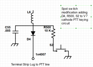
8-8-2019 Adding a “SPOT” switch to a Two: Still in experimentation but appears to be working with no issues – On V3 7054 TRANSMITTER OSCILLATOR TUBE – Inserting a diode in series on the other end of L1 that is connected to Pin 1 and on the PTT line side with cathode side oriented toward the PTT line is the beginning point. This isolates the SPOT switch from the PTT circuit so it will not activate the PA and allows the cathode of the oscillator to be grounded through a resistor at the L6 and diode connection when a SPST NO switch is pressed. To install this modification, unsolder the leads of L6 and C55 (.005 uF CD) from the terminal strip lug. Insert a 1N4004-4007 diode in series with the cathode (the end with the color band around it) connected to the terminal strip lug. Connect L6 and C55 to the anode of the diode (other end) and connect a 10 K ohm resistor that will feed the SPST NO switch. Connect a SPST NO switch with one side of the switch tied to ground and the other to the resistor that comes from the L6/C55/diode junction. Resistor values between 6.8 K and 10K with a one half watt rating appear to work properly. Above 10 k the oscillator in the first test radio would not start. I’ve done a 2nd radio and a 10 k resistor worked in it. The .005 capacitor must be connected to the anode of the diode/L6 connection to bypass RF to ground at that point or the circuit does not work correctly.
The signal is pretty strong and overloads the RX but finding the TX frequency does work. Installing a shield on V1 RF amp and the TX oscillator tube if its missing helps reduce the overload. If the volume control is turned up, the speaker will have feedback when the frequency is spotted.
Feedback or “Howling” at the highest volume control setting: This has appeared in a 2 Messenger One’s and in a Two. I spent a couple hours trying to figure out what was going on. Tube substitution with known good tubes, checking/substituting electrolytic capacitors (can capacitor), shielding tubes, etc. First of all, a One had a 12AX7 in place of the 12AU7. Once the 12AX7 was replaced, the issue was reduced. In another instance, I eventually found the culprit. There is a 470K ohm resistor coming off pin 2 or 8 of the 12AB5. In all cases, this resistor was reading around 540K ohm or more. Replacing this resistor with a 470k ohm fixed the problem. Since this resistor was off value, I also checked the resistors around the detector and other audio amp stages. Usually I would find a few resistors in the hundreds of K ohms that were out of tolerance or borderline. Replacing these did help performance. Sometimes the cathode resistors in the IF and RF amp stage also change values. You may want to recheck the IF alignment after replacing some of these resistors.
The 470K ohm resistor on the 12AB5 helps set the grid bias voltage and since we have raised the plate voltages with the rectifier tube change out to semiconductor diodes, this appears to have changed the bias. Reducing that value below 470K ohm might resolve a stubborn feedback issue if a 470K ohm only reduces it.
Issues With Frequency Netting:
TX Exceeding PLUS or MINUS 1KHZ off frequency: If you find your TX frequencies are more than about + and – 800 hz from center frequencies, try retuning L7 (TX oscillator plate coil) while watching the frequency counter for the lowest frequency reading (a slight dip) on any channel and then net the crystals to balance the frequency spread with L5. Sometimes the frequency error can be as much as 10 KHZ or more and makes it appear that all of the TX crystals are off frequency.
Crystal controlled RX OFF FREQUENCY: If the warping coil does not pull the RX crystals on frequency, more than likely the 455 khz IF transformers are not tuned to 455 khz. The transformers should be peaked with a 455 khz signal injected into the mixer, per the manual. Failure to tune the IF transformers correctly can result in the RX crystals not netting on frequency and be off more than 10 KHZ. The 29.000 mhz signal is mixed with the 28.545 mhz oscillator signal (if its on frequency) and results in a 455 khz signal that passes through the IF transformers. If the IF transformers are tuned to 465 or 445 khz (10 KHZ higher or lower) then the RX will be off frequency that amount as the IF filters are narrow.