
Background Info
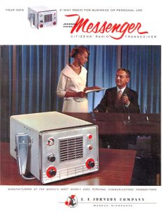
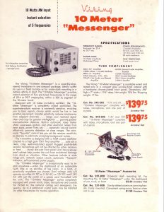
Johnson Messenger Ones and Two’s were early to mid 1960’s vintage CB radios that were popular at the time. Johnson also offered the Viking Messenger 10 Meter, which was a Messenger One that offered higher input power with 2 component changes internally but was otherwise identical with the CB version.
The Messenger One was a 5 channel, crystal controlled receiver and transmitter combined on a single chassis with power supply, It uses a single conversion receiver with 455 khz IF and the receiver crystals oscillate 455 khz below the transmitter crystal frequency. Both the One and Two were capable of both mobile (6 or 12v with 12v being the most common using the appropriate vibrator) and base station (120 v AC) operation. There was a 120 v AC base station only version made. Receiver sensitivity is rated around 1 uv for both radios. All models use the same style 9 pin female octal style plug wired for mobile or base station use. BEWARE that sometimes the “key” on the octal plug on the radio gets broken off and if that should happen, you can kill the radio by inserting the plug where AC is applied to the wrong pins. Also many of the 120v AC cables have had the dual fused plug removed and this provides no protection if something goes bad inside the radio.
Both models use a high impedance microphone. If yours is missing the mic, be prepared to improvise. The SAMS photofacts for a Messenger One states a ceramic microphone was used. Usually the microphone is hard wired inside the radio and exits the case through a slot cut in the case on the underneath through a rubber grommet that usually has severely deteriorated or even missing. I understand 2 styles of microphone were used. Turner supplied a small “tape recorder” style metal mic and a momentary spring loaded PTT switch. I’ve heard these called “Ice Cream Cone” mics. The other style is a palm microphone, similar to the style of most hand held microphones on radios of today. In the above advertisements the 10 meter version shows the palm mic and the CB versions show the cone shaped mics. Either one would be correct for your radio. Look in Hints and Mods for more info and using a modern replacement mic.
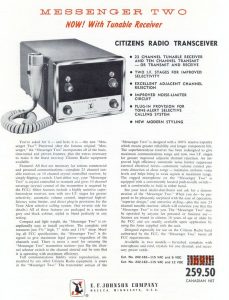
The Messenger Two was an improved version of the One. It has 10 crystal controlled RX and TX channels, a more selective receiver (two extra 455 khz IF transformers and an extra stage of IF amplification) and on the later models included a selectable VFO/crystal switch for the RX. If you economized and only purchased TX crystals, the switch disabled the RX crystal oscillator when switched in but the channel selector will TX on the selected channel.
On the rear panel there are one or two additional round female octal style plugs that were used for accessories of a Two. Proper operation of the Two requires either the matching accessory male plug to be plugged in or one of the accessory devices. The “dummy” plugs have internal jumpers and bypass capacitors. If your Two is missing these, it’s easily jumpered on the back of the connector inside the radio or you may opt to remove the wiring and do away with any extra sources of hum, since audio and squelch is routed through them.
The CB technician of the day usually performed a couple of hacks on the radio to increase it’s power output. A 3900 ohm 10 watt (2200 ohm 5 watt on some schematics) resistor provides modulated B+ to the plate of the 7061 PA amp tube and limited the power input to FCC specifications which meant around 3 watts of output. Usually the tech would either change the resistor to a lower value or more commonly place a wire across it and this was called “strapping it” or “jumping it”. This resulted in an increase of power output, usually to around a 5 watts more. The 10 meter Viking Messenger version used a 390 ohm resistor with a .33 uf capacitor in parallel in place of the 3900/2200 ohm resistor. I include a 3 watt 390 ohm metal oxide resistor with a .47 uF capacitor in my refurb kit to restore the radio to perform as the amateur version did.
The other hack was the replace the 6BW4 or 12BW4 rectifier tube with diodes. The diodes of that era did not have very high PIV ratings so they put several in series and stacked them vertically where the tube plugged in. It usually had a tripod look and was called “the Christmas tree” referring to its conical, Christmas tree shape. This has an effect on power output as it raises the B+ about 70-80 volts higher. It also results in less heat from that area of the radio, as a 12BW4 draws 450 ma for the filament alone in a 12 volt radio. Beware – The HV usually rises to just under the 450 volt rating of the filter capacitor and some of the “cheap” Chinese capacitors don’t last long at their maximum ratings. I typically see around 7-8 watts of output with the 390 ohm resistor/capacitor and solid-state diodes installed.
I recall seeing an external S meter added to a One in the early 70’s. A Messenger 223 was the next generation 23 channel base that used a One chassis with a solid-state crystal synthesizer and a had an S meter. That circuit was more than likely added to a One or Two for an S meter by a technician of that era as an upgrade to a One or Two.
Occasionally you may find a radio that has an external crystal socket or sockets added so you could plug in crystals and overcome the limitation of the number of channels which required removal of the case to change. I have seen a few that microphone connectors were added to the side or to the front panel. Usually the side panel connector used the large Amphenol 4 pin round metal plug that is difficult to find today. Sometimes you will find one with a 4 pin modern style 4 pin microphone connector installed into the front panel.
If your radio has one of the large Amphenol connectors and you do not have the matching male connector, it an be removed and an aluminum square plate can be mounted over it to cover the hole. A hole can be bored in the plate and a modern 4 pin microphone connector used. The cases of these modified radios either have a hole or slot cut into the side to allow the case to slide over the connector or to remove the connector for case removal. I use an aluminum squars to cover that hole in the chassis so small fingers can’t be inserted and exposed to shock hazard and then drill to to mount a modern 4 pin connector.
With today’s LED lighting the old Messenger Two radios are just begging for LED upgrades for the 1815 indicator lamps. The Messenger One radios used neon bulbs instead of the 1815 lamps.
If you have one these old workhorses I would recommend replacing all the electrolytic and encapsulated molded paper capacitors. I’ve seen several of the encapsulated paper capacitors that have cracks or split open and almost always the 82 uF 450 volt capacitor has a bulge, crack, or even leaking from the rubber end cap if OEM.