
SERVICE INFO
The best source of schematics and service information is www.cbtricks.com for the Johnson Messengers. There are other sources elsewhere on the internet that you can obtain service information from. CBTRICKS was offline for a few months in late 2020 and if this should happen again, the site is backed up on the Wayback Machine, available at www.archive.org. Perform a search on cbtricks.com and then select sometime in mid 2020 to view the archive. Then browse to the files section and find what you need. One and Two schematics and service information are available there.
IMPORTANT NOTE: The Messenger One series has different versions and it may take some studying to determine which schematic you need. The SAMS photofact manual on CBtricks is for what I believe to be the early version of the Messenger One, after having one come across the bench. The noticeable differences between it and the later versions I have seen were no ANL diodes in it and the RFC coils were larger, molded plastic encased and light blue with colored bands. I have a picture of the underneath further down the page that shows this version. The later version radio RFC’s are smaller, look like they were dipped in some kind of coating, and are dark red or brown with color bands. The early version One used both diode sections of the 6AL5, one for detection/avc and the other for noise limiting. The later Ones added 2 diodes for noise limiting/avc control and only used one diode section of the 6AL5 for detection which left some pins on the tube socket not connected to anything. There are a few other circuit differences between the early and later models.
This applies to both One and Two radios. Determine if your radio is a 117 V AC only or offers both AC/DC operation via 12 volt or 6 volt DC. Vibrators are labeled with voltage they operate at but it is possible someone has changed it and used the wrong one or it is missing. The easiest way other than model number is to look at the PA and audio amp tubes. If the above tubes are 6CM6, the radio is a 6 volt version. If they are 7061 and 12AB5, it’s a 12 volt version. The rectifier, PA, and modulator tubes in the 6 volt radio are 6 volt filaments instead of 12 volt versions in the 6 volt version. Before conversion, verify the radio is operating on 27 mhz. If not, it is easier to troubleshoot and repair issues before tuning any coils or capacitors.
Missing Tube Shields: I don’t know if the radios were shipped with many missing tube shields or if they have been “lost” over the years. The most important one that should be installed is the mixer tube. I’ve found radios that had all of the original EF Johnson labeled tubes in them and the shields were missing except for the mixer and TX oscillator. If you have some extra shields available, shielding V1 RF amp would have priority over others. When a 7054/12BY7A is used in V7 the shield helps reduce spurious oscillations on channels with no transmit crystals installed as well as reduces the radiated signal if a SPOT switch is added.
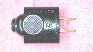
NOTICE: When you remove the cover, there are dangerous voltages that can seriously injure or kill you. Observe all safety precautions as there can be as much as 450 vdc present on the high voltage circuit. The OEM 120 v power cord came with a plug that had 2 fuses in it. A local source may be a farm store that sells electric fence accessories. “DARE 1624” is stamped on those and on new ones available on Ebay. Check those fuses to make sure they are not more than about 1.5 amps. If your cord is missing the AC plug fused connector, you should look at installing a fuse for the AC line on the chassis and using a modern, polarized 2 wire plug or a 3 wire plug with earth ground and wire accordingly.
The crystal selector switch wafers and the VFO/Crystal switch on the side may require some cleaning with Deoxit D100L. Just click on the bottle above to view it on Amazon and purchase. This size seems to be the least expensive bang for your buck and a drop or two is all you need to fix most problems. The brush is good for some of those hard to reach places that the squeeze tube version isn’t able to get to. You can also use it on noisy potentiometers and other switches, such as PTT, tube contacts, and the crystal socket contacts. Do not saturate the crystal switch selector wafers, use a q tip or the brush and put just a drop or two on the contact surface and then clean by turning the switch many times. Wipe off any access. Avoid the spray can as it dispenses more than you need and has a lot of waste from over-spray.

Missing Accessory Plug(s) on a Two or Microphone on One or Two: If your accessory plugs are missing, you will have to either jumper the connections on the back side of the connectors or remove the wiring and bridge the connections on the chassis unless you make up new plugs. If your microphone is missing, you will have to ground the “red” wire to enable the RX or “black”wire to turn on the TX. Refer to the schematic for that information.
The microphone is a high impedance type. The SAMS manual states it is a CERAMIC type. Low impedance microphones are most commonly found today. An Astatic D104 or a Turner +2 or +3 mic would all be good choices if you are missing the microphone. If you must replace the original mic due to damage, try to salvage the cartridge and use in the replacement mic if its good. 500-600 ohm dynamic mics will work but the modulation is reduced.
Examine the radio to determine if any previous mods were performed. Some things to look for is a missing rectifier tube or bridging the 3900 ohm 10 watt resistor with a wire. Make a note of it. If the 3900 ohm resistor is bridged, you should remove the shorting wire. If you want the extra power, replace the 3900 ohm resister with a 390 ohm resistor and a .33 uF to .5 uf capacitor (.47 uF 630V or 400V is included in my refurb kit) in parallel with the resistor.
Before powering up: Inspect all the electrolytic and encapsulated molded capacitors. Look for any swelling, bulging, leaking, or cracking. According to Cliff WB4NKL, Sprague black body molded capacitors with RED LETTERING are mylar type and do not normally require replacement. White lettering are paper type and should be changed. I always change out C59, the 80 uf electrolytic capacitor BEFORE TURNING THE RADIO ON THE FIRST TIME because in almost all cases it has failed or ready to fail with swelling, leaking, or cracking of the rubber + side end cap. I have found 100 uF 450 volt 18×36 mm radial lead capacitors are a good fit under the chassis at the rectifier tube socket with the 1N4007 diodes soldered under there also. BEWARE: Some of the cheap China brands won’t last for more than several hours of continuous use as they don’t like being pushed to near the maximum voltage rating. They overheat and swell, with the symptom becoming hum in the speaker and sometimes releasing an odor from my personal experiences.
The bracket holding C59 in place usually has to be cut to get the capacitor out. The steel is tough and you can bend it to help hold a replacement capacitor if you choose to put C59 back on top. The capacitor in my refurb kit will fit in the space under the rectifier tube if you wish to place it there. When replacing C59 with an under chassis capacitor, cover the exposed end of the wire or remove the wire that fed the original C59 on top of the chassis as it is a shock risk if you choose not to place a replacement capacitor in that area. Remove the rectifier tube and replace it with the diodes if you put the capacitor under the tube socket because that is a high heat area with the tube installed and will lessen the life of the capacitor. Do not use less than a 450 vdc part for C59, as the B+ is usually increased to just under 450 vdc when the rectifier tube is replaced with silicon diodes.
NOTE: If you drill the rivet out that held C59, that hole can be used to mount a chassis mounted fuse holder and convert to a polarized type AC plug. One of the wires going to the switch is cut, rerouted to the fuse holder, and then the switch is reconnected via a wire splice to the other side of the fuse holder.
If you are not going to use the radio with a DC supply, C56, a .5 uF molded capacitor does not have to be replaced and can be left in or removed. A .47uF capacitor is an acceptable replacement and included with my refurb kit.
The 2 section C28 is replaced by 2 capacitors in a Two. If you have a One, there are usually separate 4 uF (replaced with 4.7 uF) and 8 uf (replaced with 10 uF) capacitors. If the 8 (or 10 uF) capacitor is open or missing, the relay will vibrate and you will hear “buzzing audio” that is induced in the relay from the modulated audio on transmit. All electrolytic multi-section replacement capacitors can be mounted under the chassis and the C33 can capacitor can be cut loose from the circuits underneath and left in for cosmetic appearances. If you choose not to install the capacitors for C33 and there is squealing or howling in the speaker, especially at high volume, that is an indication of one of the internal caps could be bad. Also inspect the volume control as sometimes these get changed and if not the correct value, it will cause the same symptom. If it looks like it has been changed, verify it’s a 1 meg ohm. Lower values are what cause the howling issue. A 470 K ohm resistor from grid to ground on the 12AB5 that is out of tolerance can also cause feedback at high volume.
After replacing the capacitors: It’s time for a tune up on 27 mhz. Inspect all the tubes and see if the filaments are lit. If any look extremely dim or dark, wiggle the tube around to determine if corrosion is preventing the filament from lighting. In 12 volt DC radios, 6 volt tubes are in series or paralleled with others so try wiggling other tubes in the RX stage if one isn’t lit before removing to check or replacing. In a Two, if V4 looks very dim compared to the other tubes, check R53 (43 ohm 2 watt resistor) coming from Pin 9 of V10 to ground near the large microphone connector hole. I’ve seen a few bad solder joints on the tube/resistor connection.
The alignment information in the service manual gives the specs the radio is rated for and it may require some alignment to meet them. I substitute a 100 mhz oscilloscope for the VTVM and it works just as well for tuning the RF/IF stages. Tune for maximum signal on the scope. Power output can be anywhere from about 3-4 watts on an unmodified radio to well over 5 watts on a modified one. 7-8 watts seems typical for the increased HV from solid-state rectifiers and the 390 ohm resistor mod for a 7061. 6CM6 tubes seem to have a little more output than that but seem more touchy on neutralization.
If you experience any issues with hum in the RX/TX audio: I’ve found 2 radios with bad 6AW8A tubes. They had internal cathode to heater shorts. If the squelch doesn’t work properly, the 6AW8A tube may have been substituted with a similar tube and none of the substitutes perform as well that I have tried. They work but audio is slightly reduced and the squelch that doesn’t work very well to begin with becomes even worse.
If the RX sensitivity seems a little weak or requires an extremely strong signal, check the RELAY CONTACTS FIRST!!!! Dirty contacts on the relay seem to cause more issues than almost anything else. Out of tolerance of hundreds of K ohm resistors in the detector and ANL circuits also contribute to poor sensitivity. If any of those resistors are out of tolerance more than 10%, change them! The 470K ohm resistors are almost always bad.
If the issue is not the relay, you can try swapping V1 with one of the other 6BJ6 tubes used in the IF stages and see if that offers any improvement. Sometimes the gain at 27/29 mhz is degraded on V1 but it will work well in the IF stage at 455 khz and swapping will cure this and although the tube is weak, it will work fine at the IF frequency.
Proper alignment of the RX crystal frequency, IF, mixer, and front end stages are critical for maximum sensitivity. You can try the tube swap modification I have listed on my Hints and Mods page if you find the sensitivity is just not what you think it should be and look there for more things I have discovered that affect receiver sensitivity.
Once you have confirmed the receiver and transmitter are working properly, its time to begin the conversion to 29 mhz.
Installing the crystals – There are different ways to install your new crystals. The easiest way is remove the old CB crystals, spread the leads on the new crystals, push them into the crystal holder, and then solder the leads from the top side. You can solder the crystals under the crystal holders but the last couple of crystals near the bracket are a very tight fit and you have to get a bit creative to get them in there and soldered. You can “rebuild” the existing CB crystals by desoldering the case from the base and then remove the fine wires and white crystal disk that is soldered to the base leads. Trimming of the base leads may be required as the lengths vary from each manufacturer. The crystal housing cover can be left off or with lots of care and patience, can be soldered back on so the crystal looks “stock”. If you solder the crystal can cover back on, excess solder can short the crystal inside to the case.
I start with the crystal controlled channels on the receiver and then do the tunable RX if its a Two. If you have a One, VFO tuning does not apply as the RX is crystal controlled. Just follow the alignment instructions in the manual and substitute your 29 mhz RX frequencies for the 27 mhz frequency.
I set the VFO to approximately Ch 10 on the dial. Adjust C110 on the bracket next to the 12BE6 mixer and above L113 to over 2/3 meshed. Using a calibrated signal source with a strong signal injected into the antenna port, slowly screw L113 counter clockwise with about a .25 volt or stronger 1000 hz 30% modulated 27.5 mhz signal applied until you hear/see the signal on the scope. Then decrease the signal so it isn’t overloading the radio. You may have to rock the VFO slightly to peak the signal. Adjust L1 and T3 top core and bottom cores for maximum audio, then adjust the front end and mixer input.
Change the generator frequency to 28.00, repeat the above and then do it again at 28.5 and 29.0. Once you have moved the VFO so it is working on 29.0 mhz, you can then adjust for the 300 khz frequency range for it to cover. I set mine so 29.00 is centered on Ch 10 which allows me to tune either side. I walk it up to 29 mhz as it is much easier to align the mixer and rf amp coils a little at a time.
The receiver should now be working with around 1 uv of sensitivity or better.
VFO Tracking: The VFO is not linear in tracking and will take some work to get it close. This is a time consuming process and you will either get it close enough to live with it or maybe get it almost perfect. For CH 1 on the VFO, use 28.890 (a difference of 110 khz below Ch 10 on 11 meters) and CH 23 (180 khz above Ch 10 on 11 meters). Using an accurate signal source, adjust L113 on CH 1 (28.890) for best signal then tune the VFO to CH 23 (29.180), and adjust C110 for best signal. Change signal source back to 28.890, tune down to Ch 1, and see how much the error is. Adjust L113, change frequency on the VFO and signal source, adjust C110. Continue doing this until your VFO is tracking as accurately as you can live with. CH 10 should be 29.00 and you should check occasionally to make sure that is staying centered. Be patient, it can take many back and forth attempts to get the tracking reasonably close. You may even want to take a break and proceed to TX alignment if you have been at it awhile and losing patience. The TX adjustments have no affect on the VFO.
Follow the TX alignment instructions in the service information. Once you have tuned it , either turn to a channel with no crystal installed or unplug (if able to) a TX crystal from the socket to check for spurious oscillations. Very important!!! If the transmitter makes any power, adjust the neutralization and retune it. There should be no power output on any channel with no crystal installed. This can sometimes become challenging to get right.
NETTING THE CRYSTALS ON FREQUENCY – READ BEFORE ADJUSTING. Specifications for this radio say the frequency tolerance is .005%. Crystals that are plus or minus 1.34 khz are in spec at 26.965 mhz. Adjust the frequency adjustment coil so the highest and lowest frequencies are spaced evenly apart. If the frequency spread between the highest and lowest frequency error is more than plus or minus 1 khz, there may be a problem either with the crystal, its holder, or switch/wiring.
Go to my Hints and Mods page for tweaking the radio for maximum performance for power, modulation, and adding SPOT switch to a Two.