
I use these POE unmanaged switches in the remote sites to power the cameras. Like most “cheap” electronics from China, the manufacturer never installed any EMI suppression other than some bypass capacitors on the AC input. They emit lots of trash in the HF spectrum and it radiates through the AC line cord as my RF sniffer indicated. This is what I discovered and the steps I took to address the issues.
The ground shield for all of the RJ45 connectors is either bypassed with an SMD capacitor to earth ground or has no connection as there is no DC earth ground connection. The linking non-POE port ground shields are also DC isolated from the POE ground shield. None of the shields has a DC connection to the V- supply bus. This may be contributing to radiation of the broadband noise from the shields of all the Ethernet cables that are plugged into the device.
Installing An EMI Filter
A surplus Corcom 3R1 series EMI 3 amp filter was found on Ebay and was a good fit in the available space on the chassis. It was purchased from Ebay for about $8. This is an obsolete part but the data sheet is posted HERE. This is a 2 stage filter but a single stage filter might work almost as well although the noise suppression specifications are about half as much. I found a deal on some single stage filters from a surplus electronics place and have some on order to try in another POE switch.
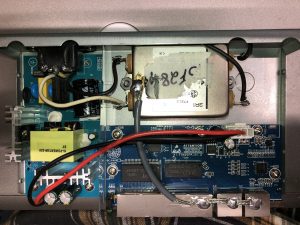
There was room within the metal case to mount it parallel to the rear of the chassis. 2 holes were drilled in the chassis and the filter was bolted in using 2 stainless machine screws with star lock washers. The line input of the filter (side with the grounding lug) was placed on the side farthest away from the power supply board to keep the AC wires going to the power supply circuit board as short as possible. The power supply board was removed from the chassis and the AC connector removed. (3) 4 inch 18 gauge insulated wires were installed in the holes where the AC plug lugs were. The power supply board was then installed back onto the metal chassis.
The AC connector was rotated 180 degrees from its original orientation (solder lugs in the board) so the solder lugs are on top and then reattached to the rear panel. The earth ground wire from the power supply board (coming from the center lug) was shortened and then soldered to the center solder lug on the AC connector. This provides earth ground to the chassis. (2) 7 inch 18 gauge wires were then soldered to the outer lugs of the panel mounted ac connector. These were routed along the rear panel and then attached to the AC line input of the EMI Filter (side that has the grounding lug on the filter). The 2 wires coming from the power supply board were then attached to the load output side of the EMI filter after trimming the plastic insulating shield and folding down a small area so it would not cut into the wires. This completes the installation of the EMI filter.
Earth Grounding RJ45 Shields
I was not happy with the DC isolated RJ45 grounding shields so I soldered a ground braid to each RJ45 shield and then soldered that to the shield of the Corcom EMI Filter. All shields are now DC grounded to the chassis (earth ground). One last addition was to add ferrites to the AC cord. I blew out the case with compressed air to remove any metal shavings from the drilling that might have remained under the circuit boards, reassembled, then tested.
Previously on 10 meters the unmodified POE switch radiated noise that was about S5 and my background noise would drop to about S2 when unplugged. Now I can detect no rise in background noise when plugging in the POE switch. I deem this project a success!